
Winding lead exits
Supplementary insulation and routing protection where winding conductors leave the coil assembly.
TRANSFORMER ENGINEERING GUIDE
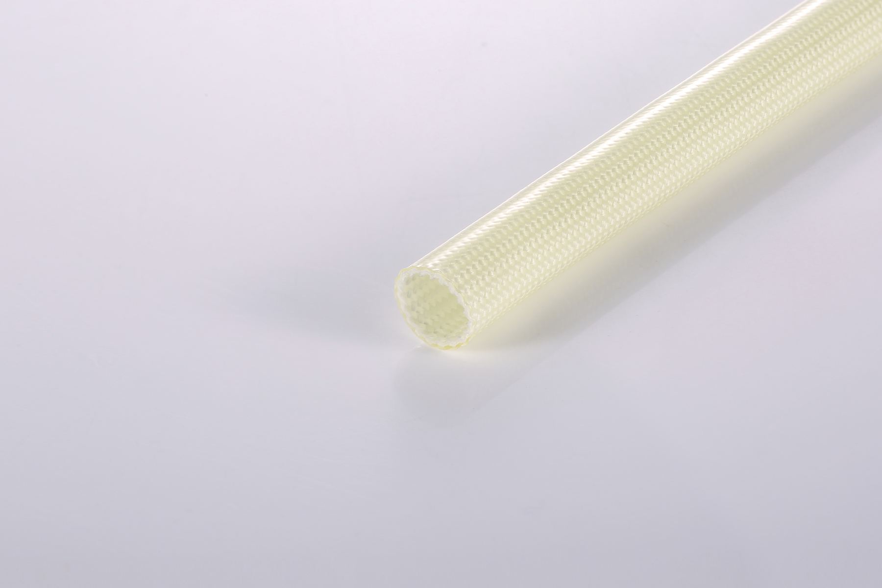
Transformer lead exits and winding connections require coordinated thermal, dielectric and mechanical protection. Evaluate fiberglass sleeving with the insulation system, conductor size, impregnation process and end-use approval route.
APPLICATION POSITIONS
Supplementary insulation and routing protection where winding conductors leave the coil assembly.
Electrical and mechanical protection around joined conductors, transitions and lead-wire interfaces.
Controlled insulation coverage near terminals and constrained assembly spaces.
QUALIFICATION CHECKLIST
A nominal sleeving rating does not approve the complete transformer. Confirm the final construction through the applicable system and end-product validation process.
RELATED RESOURCES
Review a 200°C-class, typical 600V coated fiberglass construction.
View product detailsDefine dielectric requirements together with temperature and dimensions.
Read the guideCompare motor lead-wire routing, vibration and thermal requirements.
Read the guideTRANSFORMER PROJECT SUPPORT
Include transformer type, thermal class, voltage test, wire size, varnish or oil exposure, approval target, current model and estimated demand.