
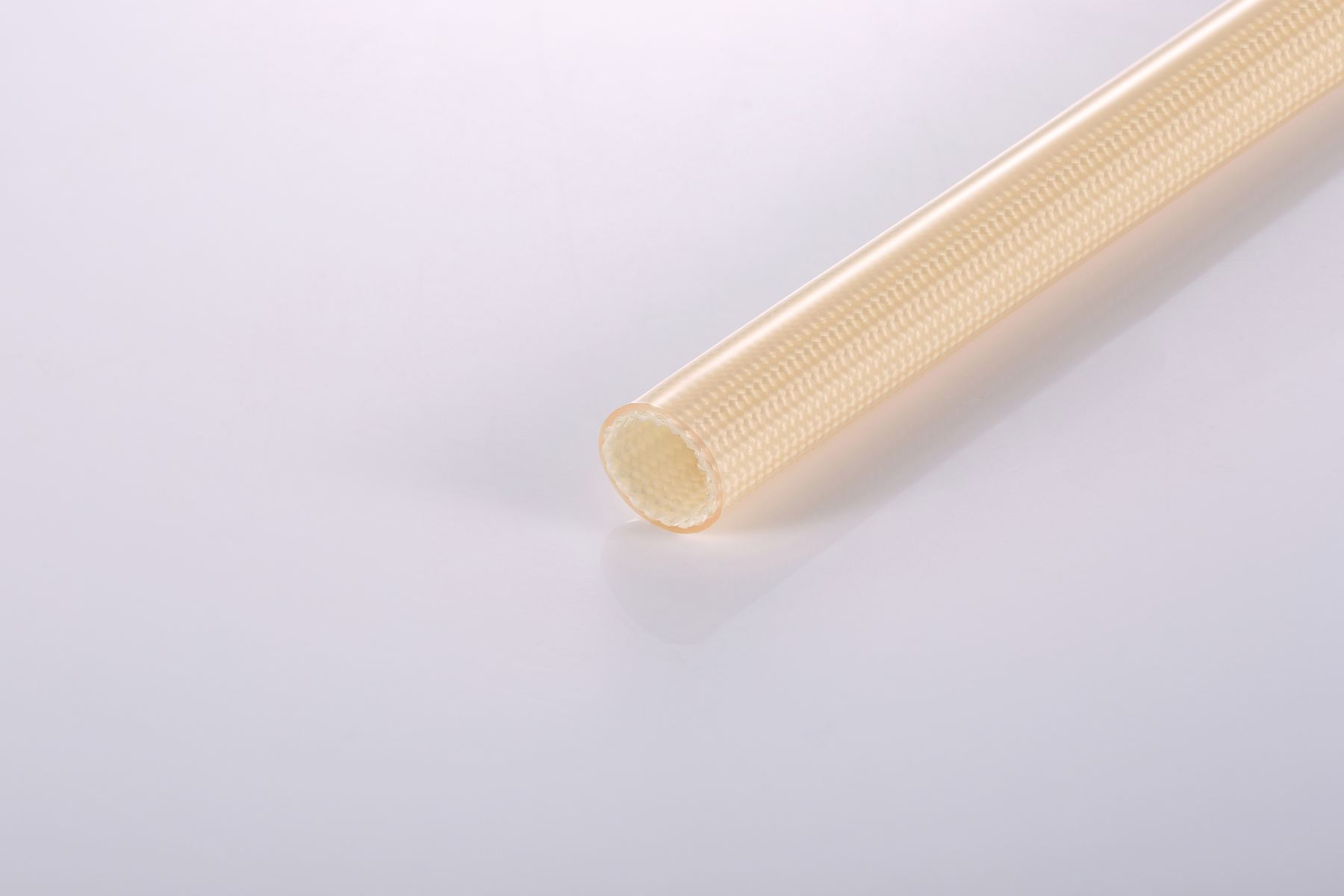
Acrylic fiberglass sleeving
A common 155°C-class direction for electrical insulation projects where dimensional stability, oil resistance direction and cost balance matter.
ENGINEERING SPECIFICATION GUIDE
A useful fiberglass sleeve specification defines more than a nominal diameter. Record the conductor size, sleeve inner diameter, wall build, coating, temperature, voltage, mechanical exposure and validation target so the selected construction can be reviewed against the actual assembly.
CORE PARAMETERS
| Parameter | What to specify | Why it matters |
|---|---|---|
| Inner diameter and tolerance | Target ID, maximum finished conductor OD and installation clearance | Controls insertion fit, coverage and routing around terminals or bundles |
| Wall build and coating | Coating family, nominal wall direction and any space limit | Changes flexibility, abrasion behavior, dielectric performance and installed outside diameter |
| Temperature conditions | Continuous temperature, peak temperature, duration and thermal cycling | Coating selection must reflect conductor hot spots, not ambient temperature alone |
| Electrical requirement | Operating voltage, dielectric test method and insulation-system requirement | Nominal voltage must be assessed with wall build, dimensions and end-use validation |
| Environment and assembly | Bend radius, abrasion, vibration, varnish, oil or fluid exposure | Determines whether the construction remains suitable after installation and service |
| Supply requirement | Color, roll or cut length, quantity and required documents | Supports sample planning, production consistency and quotation accuracy |
MATERIAL DIRECTION
A common 155°C-class direction for electrical insulation projects where dimensional stability, oil resistance direction and cost balance matter.
A 200°C-class direction for higher-temperature electrical assemblies. Review wall build, dielectric test and final system validation for the selected grade.
View silicone resin specificationsA flexible 200°C-class direction for motor leads and routed harnesses where bending and handling are important.
DIMENSION CHECK
Measure the largest finished outside diameter of the wire, splice, terminal or bundle that must pass through the sleeve. Then define a target inner diameter with enough assembly clearance while avoiding unnecessary looseness.
A nominal 4 mm, 10 mm or 20 mm sleeve is only a starting point. The required clearance depends on the actual shape, bend route, coating, sleeve tolerance and installation method. A production-representative sample fit test is the reliable approval step.
Read the fiberglass sleeve size guideRFQ CHECKLIST
Catalog values are a selection starting point. Confirm the final material grade, drawing, test method and end-use conditions before production approval.
RELATED GUIDES
Verify the exact product construction, UL file, test method and approval scope before specifying a flame-test classification.
Read the UL VW-1 guideDefine voltage together with wall build, temperature, dimensions and validation conditions.
Read the voltage guideCompare continuous temperature, peak exposure and coating chemistry.
Read the temperature guideReview motor lead-wire routing, vibration and thermal requirements.
Read the motor guideSPECIFICATION SUPPORT
Include the current part number or sample when available. WCW can review dimensions, material direction, test requirements and sample options for your application.