
Measure the real lead route
Use the largest finished wire, splice or terminal section that must pass through the sleeve. Account for shape, tolerance and installation sequence, not just the bare conductor diameter.
TRANSFORMER SPECIFICATION GUIDE
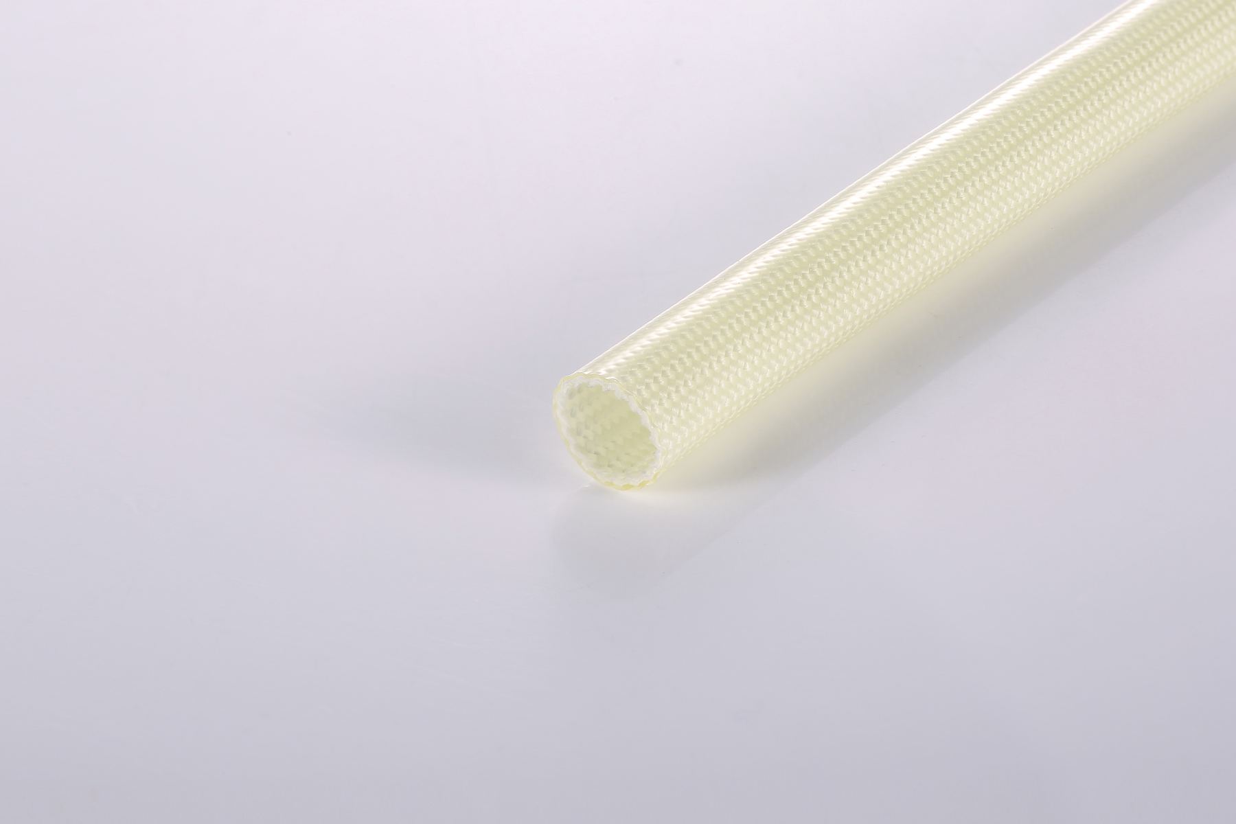
A transformer lead sleeving specification should define the installed lead condition, not just a nominal sleeve size. Combine dimension, wall build, coating, thermal class, dielectric requirement, impregnation exposure and final validation criteria before approving a production construction.
CORE SPECIFICATION FIELDS
| Field | What to specify | Why it matters |
|---|---|---|
| Lead and sleeving dimensions | Maximum finished lead OD, target inner diameter, tolerance and cut length | Controls insertion, coverage, terminal clearance and installed fit |
| Wall build and coating | Construction direction, coating family and installed space limit | Changes flexibility, outside diameter and electrical/mechanical behavior |
| Thermal conditions | Insulation-system class, conductor hot spot, peak exposure and duration | Helps select a construction compatible with operating and aging conditions |
| Electrical requirement | Operating condition, dielectric test method and applicable system requirement | Nominal material ratings do not independently approve the completed transformer |
| Process and environment | Varnish, oil or fluid exposure, curing process, bend route and abrasion risk | Confirms the material remains suitable after manufacture and in service |
| Approval package | Required documents, sample plan, test record, color and annual quantity | Creates a traceable path from quotation through production approval |
SPECIFICATION PRINCIPLE
Use the largest finished wire, splice or terminal section that must pass through the sleeve. Account for shape, tolerance and installation sequence, not just the bare conductor diameter.
Temperature direction, dielectric requirement and flame-test classification describe different validation topics. Review the exact construction and supporting documentation for each project.
When varnish, resin, oil or a curing process is present, verify the completed assembly and process route with representative samples before production release.
DIMENSION AND CLEARANCE
Too little clearance can damage the sleeve during installation or cause incomplete coverage near a terminal. Excessive clearance can affect routing, coverage control and installed appearance. Define a target inner diameter with the actual lead geometry, bend route and assembly method in mind.
Wall build also affects the finished outside diameter. Confirm the required electrical and mechanical direction together with available space around windings, bobbins, terminal boards and adjacent components.
Read the sleeving size guideRFQ CHECKLIST
Published data are a starting point for material selection. The final transformer construction must be confirmed against the applicable insulation system, end-product standard and validation process.
RELATED RESOURCES
Start with the application positions, insulation system and project qualification conditions.
Read the selection guideReview common dimensions, coating systems, temperature and voltage fields.
Read the general specification guideCoordinate dielectric requirements with wall build, dimensions and validation conditions.
Read the voltage guideReview a coated fiberglass construction for higher-temperature electrical assemblies.
View product detailsSPECIFICATION SUPPORT
Include lead dimensions, insulation-system condition, temperature, dielectric requirement, process exposure and document target. WCW can review the material direction and sample route for the specific assembly.